SIMULATION OF INVERTER FED INDUCTION MOTOR DRIVE WITH LABVIEW
Electrical and Electronics Project by Ravi Devani
ABSTRACT
This paper describes a software approach for modeling inverted fed induction motor drive using Laboratory Virtual Instrument Engineering Workbench
(LabVIEW). The reason behind the selection of LabVIEW software is because of
its strong graphical interface, flexibility of its programming language
combined with built-in tools designed specifically for test, measurement and
control. LabVIEW is generally used in most of the applications for data acquisition,
test and control. In this paper, inverter and induction motor are modeled using
LabVIEW toolkits. Simulation results are presented and are validated.
Keywords—Induction motor, LabVIEW, State model.
INTRODUCTION
MATHEMATICAL models of electrical machines are used to learn about their
dynamic characteristics using simulation tools. With the advancement of
computer technology, the drawbacks of conventional simulation methods become
more and more obvious. With the rapid growth in computer hardware and software
techniques, new user friendly simulation software packages are now available. Putting
virtual instruments software into mathematical modeling and analysis of
electrical machines will result in not only the cost reduction of the hardware
but also the enhancement of the teaching or training effect. The direct application
of this sort of software drastically simplifies simulation procedures for
several practicing engineers. LabVIEW programs are called Virtual Instruments
(VI) because their appearance and operation imitate physical instruments, such
as oscilloscopes and multi-meters. LabVIEW is a graphical programming language
for data acquisition, analysis and presentation. The components of LabVIEW are
front panel and block diagram. The front panel is built with controls and
indicators and the block diagram contains the pictorial representation of
source code. At present, LabVIEW simplifies the scientific computation, process
control, research, industrial applications and measurement applications. MATLAB
is a high performance language for technical computing. It integrates
computation, visualization and programming in an easy-to-use environment where
problems and solutions are expressed in familiar mathematical notation. MATLAB simulink
block sets are widely used in simulation of all kind of systems. MATLAB was
used for simulation of vector control of induction motor and different electric
motors. But Simulink lack the imitation of physical instruments or equipment in
appearance and operation. Considering the above, LabVIEW is used as a
simulation tool to model inverter fed induction motor drive. Field oriented
control of induction motor drive using LabVIEW was discussed in but simulation
results were not explained clearly. LabVIEW was used to simulate and find the
characteristics of synchronous generator but the speed-torque characteristics
were not explained. LabVIEW was used to identify the induction motor parameter,
automatic testing for DC motor of portable washing machine, harmonic
measurement, speed control of stepper motor, fault diagnosis of induction motor,
etc. modeling of inverter and induction motor using LabVIEW is not discussed in
literature. In this paper, LABVIEW is used as a simulation tool to model the
inverter and induction motor. The induction motor state equations are
constructed in LabVIEW environment using control design and simulation toolkit,
math script node and simple VIs. Inverter is constructed using simple VIs.
Electrical and Electronics Project by Ravi Devani
INVERTER MODEL
Voltage fed inverter receives DC voltage at one side and convert it to AC
voltage. The AC voltage and frequency may be variable or constant depending on
the application. Voltage fed inverter is used extensively for AC motor drive,
induction heating, UPS etc. In voltage fed inverters, transistor family devices
are generally preferred because of self-commutation and high switching
frequency. When a new converter circuit is developed, or a control strategy of
a converter or drive system is formulated, it is often convenient to study the
system performance by simulation before building the breadboard or prototype.
The simulation not only validates the system’s operation, but also permits
optimization of the system’s performance. Besides control and circuit
parameters, the plant parameter variation effect can be studied. Fig. 1 shows
the simple simulation block diagram for a three-phase, two-level PWM inverter.
Each leg of the inverter is represented by a “switch” which has three input
terminals and one output terminal. The output of a switch (Va0, Vb0 or Vc0) is
connected to the upper input terminal (+0.5 Vd ) if the PWM control signal (middle
input) is positive. Otherwise, the output is connected to the lower input
terminal (-0.5 Vd). The output or Va0 voltage thus oscillates between +0.5Vd
and -0.5Vd, which is characteristics of a pole of an inverter. The output phase
voltages are constructed by the following equations:


Fig. 1 Block diagram codes for modeling of inverter
INDUCTION MOTOR MODEL
State space equations are used to solve linear and nonlinear system
equations. In state space representations, any nth order differential equations
describing a control system could be reduced to n 1st order equations. These
equations are arranged in the form of matrix equations to find the solution
easily using software tools. This method is named as the state variable method.
The selection of state variables depends upon the system structure and the goals
of study. The state variables chosen for induction motor are stator currents
and rotor fluxes. Torque is calculated from the state variables and motor parameters.
The continuous state space representation of the induction motor is as follows:

The state variables are d and q-axes stator currents and rotor fluxes.

Speed is calculated from the resultant stator currents and rotor fluxes.
The equation for rotor speed is given by

The above state equations are constructed in LabVIEW using math script node
inside the simulation loop. Steps:
1. Control and simulation loop is created
2. Math script node is constructed inside the simulation loop.
3. First order differential equations are written inside the math script
node.
4. Integration is performed to find the different state variables.
5. By using simple arithmetic VIs, the speed and torque are calculated from
the stator voltages and currents.
6. Three phase stator voltages are converted into two phase quantities in
formula node.
A part of the block diagram codes framed in LabVIEW is shown in Fig. 2. The
math script node, simple arithmetic Vis and scope for measurement are
illustrated. Fig. 3 shows the speed and torque waveforms created in the front
panel using graphical display. Initially the motor runs at no load speed. At t=2.5s,
a load of 5 Nm is applied to the motor. As the motor runs at open loop
condition, speed of the motor decreases from 1497 rpm to 1480 rpm. The dq-axes
stator currents and rotor fluxes are considered as state variables. Fig. 4
shows the dqaxes stator phase currents. The dq-axes rotor fluxes are shown in
Fig. 5. The output of the inverter contains harmonics. The dq-axes stator
voltages are depicted in Fig. 6.
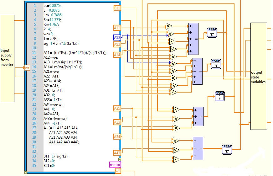
Fig. 2 Block diagram codes for modeling of induction
motor
Electrical and Electronics Project by Ravi Devani


Fig. 3 Speed and
torque waveforms of induction motor


Fig. 4 dq axes stator phase currents


Fig. 5 dq axes rotor fluxes

Fig. 6 dq axes
stator voltages
CONCLUSION
In this work, the inverter and induction motor are modeled and simulated
using LabVIEW. The models are constructed using simple VIs and mathscript node.
To prove the effectiveness of the given method, simulation results are provided.
REFERENCES
[1] G K. Matsuse, Y. Kouno, H. Kawai, J. Oikawa, “Characteristics of speed
sensor-less vector controlled dual induction motor drive connected in parallel
fed by a single Inverter”, IEEE Trans. Ind. Appl., vol. 40, pp.
153-161, Jan./Feb. 2004.
[2] K. Matsuse, Y. Kouno, H. Kawai, S. Yokomizo, “A Speed-sensor-less vector
control method of parallel-connected dual induction motor fed by a single
inverter”, IEEE Trans. Ind. Appl., vol. 38, pp. 1566–1571, Nov./Dec.
2002.
[3] H. Kubota K. Matsuse, “Speed sensorless field-oriented control of induction
motor with rotor resistance adaptation”, IEEE Trans. Ind. Appl., vol.
30, pp. 1219–1224, Sept. /Oct. 1994.
[4] H. Kubota, K. Matsuse, T. Nakano, “DSP-Based Speed Adaptive Flux Observer
of Induction Motor”, IEEE Trans. Ind. Appl., vol. 29, pp. 344- 348,
Mar./Apr. 1993.
[5] Sidney R. Bowes, Ata Sevinc, Derrick Holliday, “New natural observer
applied to speed sensorless DC servo and induction motors,”, IEEE Trans.
Ind. Appl., vol. 51, no.5, pp. 1025–1032, Oct. 2004.
[6] Young-Real Kim, Seung-Ki Sul, Min-Ho Park, “Speed sensorless vector
control of induction motor using Extended Kalman Filter”, IEEE Trans. Ind.
Appl., vol. 30, no. 5, pp.1225-1233, Sept. / Oct. 1994.
[7] Luigi Salvatore, Silvio Stasi, Lea Tarchioni, “A new EKF-based algorithm
for flux estimation in induction machines”, IEEE Trans. Ind. Electron.,
vol.40, no.5, pp.496-504, Oct.1993.
[8] Young-Real Kim, Seung-Ki Sul, Min-Ho Park, “Speed sensorless vector control
of induction motor using Extended Kalman Filter”, IEEE Trans. Ind. Appl.,
vol. 30, no. 5, pp.1225-1233, Sept. / Oct. 1994.
[9] Murat Barut, Seta Bogosyan, Metin Gokasan, “Speed-sensorless estimation
for induction motors using Extended Kalman Filters”, IEEE Trans. Ind.
Electron., vol. 54, no.1, pp. 272-280, Feb. 2007.
[10] Tao Wu, Yi-Lim Chi, Yu Guo, Chao Xu, “Simulation of FOC vector control
of induction motor based on LabVIEW”, International conference on
information engineering and computer science, IEEE, Dec 2009.
[11] M.Usama Surdar, “Synchronous generator simulation using LabVIEW”,
Journal of world academic of science, engineering and technology, vol.39,
pp.392-400, 2008.
[12] F. Filippetti, S.Pirani, L.Tommasini, G. Franceschini, “A LabVIEW based
virtual instrument for on line induction motor parameter identification”,
IEEE, pp.648-653.
[13] Chien-Lung Cheng, J.C.Yeh, S.C.Chern, Yi-Hung Lan, “Automatic testing
system based on LabVIEW for DC motor of portable washing machine”,
International Symposium on Ind. Electron., IEEE, pp.489- 493, 2008.
[14] Qiu Tang, Yaonan Wang, Siyu Guo, “Design of power system harmonic measurement
system based on LabVIEW”, Fourth international conference on natural
computation, IEEE, pp.489-493, 2008.
[15] A.Shuqiu Gong, B.Binhe, “LabVIEW based automatic rising and falling
speed control of stepper motor”, International conference on electrical machines
and systems (ICEMS 2009).
[16] Irahis Rodriguez, Roberto Alves, Victor Guzman, “Analysis of air
gap flux to detect induction motor faults”, Universities power engineering conference
(UPEC’06), pp. 690-694, Sept.2006.
[17] R. Supangat, N. Ertugrul, W. L.Soong, D. A. Gray, C. Hansen, J. Grieger,
“Broken rotor bar fault detection in induction motors using starting current
analysis”, European conference on power electronics and applications, 2005.
Electrical and Electronics Project by Ravi Devani
No comments:
Post a Comment